CYPD3123-40LQXIT USB Interface IC CCG3
♠ Product Description
| Product Attribute | Attribute Value |
| Manufacturer: | Infineon |
| Product Category: | USB Interface IC |
| Series: | CCG3 |
| Product: | USB Hubs |
| Type: | Hub Controller |
| Mounting Style: | SMD/SMT |
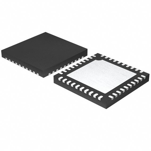
| Package / Case: | QFN-40 |
| Standard: | USB 3.0 |
| Speed: | Full Speed (FS) |
| Data Rate: | 1 Mb/s |
| Supply Voltage - Min: | 2.7 V |
| Supply Voltage - Max: | 21.5 V |
| Operating Supply Current: | 25 mA |
| Minimum Operating Temperature: | - 40 C |
| Maximum Operating Temperature: | + 85 C |
| Packaging: | Reel |
| Brand: | Infineon Technologies |
| Core: | ARM Cortex M0 |
| Interface Type: | I2C, SPI, UART |
| Number of Ports: | 1 Port |
| Operating Supply Voltage: | 2.7 V to 21.5 V |
| Port Type: | DRP |
| Product Type: | USB Interface IC |
| Factory Pack Quantity: | 2500 |
| Subcategory: | Interface ICs |
| Tradename: | EZ-PD |
♠ CYPD3123-40LQXIT EZ-PD™ CCG3 is a highly integrated USB Type-C controller that complies with the latest USB Type-C and PD standards
EZ-PD™ CCG3 is a highly integrated USB Type-C controller that complies with the latest USB Type-C and PD standards. EZ-PD CCG3 provides a complete USB Type-C and USB-Power Delivery port control solution for notebooks, dongles, monitors, docking stations and power adapters. CCG3 uses Cypress’s proprietary M0S8 technology with a 32-bit, 48-MHz ARM® Cortex® -M0 processor with 128-KB flash, 8-KB SRAM, 20 GPIOs, full-speed USB device controller, a Crypto engine for authentication, a 20V-tolerant regulator, and a pair of FETs to switch a 5V (VCONN) supply, which powers cables. CCG3 also integrates two pairs of gate drivers to control external VBUS FETs and system level ESD protection. CCG3 is available in 40-QFN, 32-QFN, and 42-WLCSP packages.
Type-C and USB-PD Support
■ Integrated USB Power Delivery 3.0 support
■ Integrated USB-PD BMC transceiver
■ Integrated VCONN FETs
■ Configurable resistors RA, RP, and RD
■ Dead Battery Detection support
■ Integrated fast role swap and extended data messaging
■ Supports one USB Type-C port
■ Integrated Hardware based overcurrent protection (OCP) and overvoltage protection (OVP)
32-bit MCU Subsystem
■ 48-MHz ARM Cortex-M0 CPU
■ 128-KB Flash
■ 8-KB SRAM
Integrated Digital Blocks
■ Hardware Crypto block enables Authentication
■ Full-Speed USB Device Controller supporting Billboard Device Class
■ Integrated timers and counters to meet response times
required by the USB-PD protocol
■ Four run-time reconfigurable serial communication blocks (SCBs) with reconfigurable I2C, SPI, or UART functionality
Clocks and Oscillators
■ Integrated oscillator eliminating the need for external clock Power
■ 2.7 V to 21.5 V operation
■ 2x Integrated dual-output gate drivers for external VBUS FET switch control
■ Independent supply voltage pin for GPIO that allows 1.71 V to 5.5 V signaling on the I/Os
■ Reset: 30 µA, Deep Sleep: 30 µA, Sleep: 3.5 mA
System-Level ESD Protection
■ On CC, SBU, DPLUS, DMINUS and VBUS pins
■ ± 8-kV Contact Discharge and ±15-kV Air Gap Discharge based on IEC61000-4-2 level 4C Packages
■ 40-pin QFN, 32-pin QFN, and 42-ball CSP for Notebooks/Accessories
■ Supports industrial temperature range (–40 °C to +105 °C)
Figure 11 illustrates the application diagram of a power adapter using a CCG3 device.
In this application, CCG3 is used as DFP (power provider) only. The maximum power profile that can be supported by power adapters is up to 20 V, 100 W using 40-pin QFN CCG3 devices. CCG3 has the ability to drive both types of FETs and the state of GPIO P1.0 (floating or grounded) indicates the type of FET (N-MOS or P-MOS FET) being used in the power provider path.
CCG3 integrates all termination resistors and uses GPIOs (VSEL0 and VSEL1) to indicate the negotiated power profile. If required, the power profile can also be selected using CCG3 serial interfaces (I2C, SPI) or PWM. The VBUS voltage on the Type-C port is monitored using internal circuits to detect undervoltage and overvoltage conditions. To ensure quick discharge of VBUS when the power adapter cable is detached, a discharge path is provided with a resistor connected to the VBUS_DISCHARGE pin of the CCG3 device. Overcurrent protection is enabled by sensing the current through the 10-m sense resistor using the “OC” and “VBUS_P” pins of the CCG3 device.
The VBUS provider through the Type-C connector can be turned on or off using the provider path FETs.
The power provider FETs are controlled by high-voltage gate driver outputs (VBUS_P_CTRL0 and VBUS_P_CTRL1 pins of CCG3 device). The CCG3 device is also capable of supporting proprietary charging protocols over the DP and DM lines of the Type-C receptacle. By providing a 5-V source at the V5V pin of the CCG3 device, the device becomes capable of delivering the VCONN supply over either the CC1 or CC2 pins of the Type-C connector.
The CCG3 family’s power adapter parts are shipped with bootloader and application firmware with limited functionality. Its purpose is to facilitate application flashing over CC line using the EZ-PD Configuration Utility. The power adapter requires an explicit power contract to be negotiated prior to enabling the EZ-PD Configuration utility to flash the application firmware.
This application firmware, based on the state of the GPIO (P1.0), determines the type of provider load switch (NFET/PFET) and supplies the 5-V VBUS over Type-C.