LPC1850FET180,551 ARM Microcontrollers – MCU Cortex-M3 200kB SRAM 200 kB SRAM

♠ Product Description
| Product Attribute | Attribute Value |
| Manufacturer: | NXP |
| Product Category: | ARM Microcontrollers - MCU |
| RoHS: | Details |
| Mounting Style: | SMD/SMT |
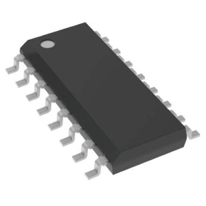
| Package/Case: | TFBGA-180 |
| Core: | ARM Cortex M3 |
| Program Memory Size: | 0 B |
| Data Bus Width: | 32 bit |
| ADC Resolution: | 10 bit |
| Maximum Clock Frequency: | 180 MHz |
| Number of I/Os: | 118 I/O |
| Data RAM Size: | 200 kB |
| Supply Voltage - Min: | 2.4 V |
| Supply Voltage - Max: | 3.6 V |
| Minimum Operating Temperature: | - 40 C |
| Maximum Operating Temperature: | + 85 C |
| Packaging: | Tray |
| Analogue Supply Voltage: | 3.3 V |
| Brand: | NXP Semiconductors |
| DAC Resolution: | 10 bit |
| Data RAM Type: | SRAM |
| Data ROM Size: | 16 kB |
| Data ROM Type: | EEPROM |
| I/O Voltage: | 2.4 V to 3.6 V |
| Interface Type: | CAN, Ethernet, I2C, SPI, USB |
| Length: | 12.575 mm |
| Moisture Sensitive: | Yes |
| Number of ADC Channels: | 8 Channel |
| Number of Timers/Counters: | 4 Timer |
| Processor Series: | LPC1850 |
| Product: | MCU |
| Product Type: | ARM Microcontrollers - MCU |
| Program Memory Type: | Flash |
| Factory Pack Quantity: | 189 |
| Subcategory: | Microcontrollers - MCU |
| Tradename: | LPC |
| Watchdog Timers: | Watchdog Timer |
| Width: | 12.575 mm |
| Part # Aliases: | 935296289551 |
| Unit Weight: | 291.515 mg |
♠ 32-bit ARM Cortex-M3 flashless MCU; up to 200 kB SRAM; Ethernet, two HS USB, LCD, and external memory controller
The LPC1850/30/20/10 are ARM Cortex-M3 based microcontrollers for embedded applications. The ARM Cortex-M3 is a next generation core that offers system enhancements such as low power consumption, enhanced debug features, and a high level of support block integration.
The LPC1850/30/20/10 operate at CPU frequencies of up to 180 MHz.The ARM Cortex-M3 CPU incorporates a 3-stage pipeline and uses a Harvard architecture with separate local instruction and data buses as well as a third bus for peripherals. The ARM Cortex-M3 CPU also includes an internal prefetch unit that supports speculative branching.
The LPC1850/30/20/10 include up to 200 kB of on-chip SRAM, a quad SPI Flash Interface (SPIFI), a State Configurable Timer/PWM (SCTimer/PWM) subsystem, two High-speed USB controllers, Ethernet, LCD, an external memory controller, and multiple digital and analog peripherals.
• Processor core – ARM Cortex-M3 processor (version r2p1), running at frequencies of up to 180 MHz.
– ARM Cortex-M3 built-in Memory Protection Unit (MPU) supporting eight regions.
– ARM Cortex-M3 built-in Nested Vectored Interrupt Controller (NVIC).
– Non-maskable Interrupt (NMI) input.
– JTAG and Serial Wire Debug, serial trace, eight breakpoints, and four watch points.
– Enhanced Trace Module (ETM) and Enhanced Trace Buffer (ETB) support.
– System tick timer.
• On-chip memory
– 200 kB SRAM for code and data use.
– Multiple SRAM blocks with separate bus access.
– 64 kB ROM containing boot code and on-chip software drivers.
– 64 bit + 256 bit One-Time Programmable (OTP) memory for general-purpose use.
• Clock generation unit
– Crystal oscillator with an operating range of 1 MHz to 25 MHz.
– 12 MHz internal RC oscillator trimmed to 1.5 % accuracy over temperature and voltage.
– Ultra-low power RTC crystal oscillator.
– Three PLLs allow CPU operation up to the maximum CPU rate without the need for a high-frequency crystal. The second PLL is dedicated to the High-speed USB, the third PLL can be used as audio PLL.
– Clock output
• Configurable digital peripherals:
– State Configurable Timer (SCTimer/PWM) subsystem on AHB.
– Global Input Multiplexer Array (GIMA) allows to cross-connect multiple inputs and outputs to event driven peripherals like timers, SCTimer/PWM, and ADC0/1
• Serial interfaces:
– Quad SPI Flash Interface (SPIFI) with 1-, 2-, or 4-bit data at rates of up to 52 MB per second.
– 10/100T Ethernet MAC with RMII and MII interfaces and DMA support for high throughput at low CPU load. Support for IEEE 1588 time stamping/advanced time stamping (IEEE 1588-2008 v2).
– One High-speed USB 2.0 Host/Device/OTG interface with DMA support and on-chip high-speed PHY (USB0).
– One High-speed USB 2.0 Host/Device interface with DMA support, on-chip full-speed PHY and ULPI interface to an external high-speed PHY (USB1).
– USB interface electrical test software included in ROM USB stack.
– Four 550 UARTs with DMA support: one UART with full modem interface; one UART with IrDA interface; three USARTs support UART synchronous mode and a smart card interface conforming to ISO7816 specification.
– Up to two C_CAN 2.0B controllers with one channel each. Use of C_CAN controller excludes operation of all other peripherals connected to the same bus bridge See Figure 1 and Ref. 2.
– Two SSP controllers with FIFO and multi-protocol support. Both SSPs with DMA support.
– One Fast-mode Plus I2C-bus interface with monitor mode and with open-drain I/O pins conforming to the full I2C-bus specification. Supports data rates of up to 1 Mbit/s.
– One standard I2C-bus interface with monitor mode and standard I/O pins.
– Two I2S interfaces with DMA support, each with one input and one output.
• Digital peripherals:
– External Memory Controller (EMC) supporting external SRAM, ROM, NOR flash, and SDRAM devices.
– LCD controller with DMA support and a programmable display resolution of up to 1024 H
– 768 V. Supports monochrome and color STN panels and TFT color panels; supports 1/2/4/8 bpp Color Look-Up Table (CLUT) and 16/24-bit direct pixel mapping.
– Secure Digital Input Output (SD/MMC) card interface.
– Eight-channel General-Purpose DMA controller can access all memories on the AHB and all DMA-capable AHB slaves.
– Up to 164 General-Purpose Input/Output (GPIO) pins with configurable pull-up/pull-down resistors.
– GPIO registers are located on the AHB for fast access. GPIO ports have DMA support.
– Up to eight GPIO pins can be selected from all GPIO pins as edge and level sensitive interrupt sources.
– Two GPIO group interrupt modules enable an interrupt based on a programmable pattern of input states of a group of GPIO pins.
– Four general-purpose timer/counters with capture and match capabilities.
– One motor control PWM for three-phase motor control.
– One Quadrature Encoder Interface (QEI).
– Repetitive Interrupt timer (RI timer).
– Windowed watchdog timer.
– Ultra-low power Real-Time Clock (RTC) on separate power domain with 256 bytes of battery powered backup registers.
– Alarm timer; can be battery powered.
• Analog peripherals:
– One 10-bit DAC with DMA support and a data conversion rate of 400 kSamples/s.
– Two 10-bit ADCs with DMA support and a data conversion rate of 400 kSamples/s. Up to eight input channels per ADC.
• Unique ID for each device.
• Power:
– Single 3.3 V (2.2 V to 3.6 V) power supply with on-chip internal voltage regulator for the core supply and the RTC power domain.
– RTC power domain can be powered separately by a 3 V battery supply.
– Four reduced power modes: Sleep, Deep-sleep, Power-down, and Deep power-down.
– Processor wake-up from Sleep mode via wake-up interrupts from various peripherals.
– Wake-up from Deep-sleep, Power-down, and Deep power-down modes via external interrupts and interrupts generated by battery powered blocks in the RTC power domain.
– Brownout detect with four separate thresholds for interrupt and forced reset.
– Power-On Reset (POR).
• Available as 144-pin LQFP packages and as 256-pin, 180-pin, and 100-pin BGA packages.
• Industrial
• RFID readers
• Consumer
• e-Metering
• White goods